The Definitive USB Guide
22 October 2018
If you’ve been paying attention to the world of USB, you may have heard of the terms USB 3.x, Type C and USB PD. It’s not surprising that many people get confused and believe that these are similar. In fact, they are different and not always used together. So, what’s the difference?
The simple answer to this question is; USB 3.x is the USB standard that defines the connection speed and other features, USB Type-C defines the physical aspects of the interconnect (plug and receptacle) including shape and connections, and USB PD is a power delivery protocol specification which supports power delivery up to 100W with additional features. This article aims to give a brief introduction on the history of the three, how they have evolved together and current developments in USB PD fast charging.
USB 3.x, Type C, and USB PD
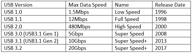
Data connectivity was the focus of the USB standards defined by the USB implementers Forum (USB-IF). This is clear in the following table which shows the evolution of USB data speed, starting with USB 1.0 through to the latest USB 3.2, providing enhanced data speed with each iteration.
Whilst power management has been part of the USB specifications the initial generations covered how the host could power a peripheral accessory and battery charging was not included. Despite the absence of guidelines in the specifications, designers still figured out ways to use USB for battery charging. As a result, products were designed which could use the USB port for charging. At that point, battery capacity of typical products (i.e. feature phone) were not large, hence the default 5V 0.5A power output from the standard USB interface met the general charging requirements.
However, due to the lack of a specification, interoperability was a major issue for these first-generation USB battery chargers. Moreover, as connected products have increased in performance (i.e. feature phones evolved into smart phones), this has led to increased power consumption and 0.5A max charging current became a limiting factor in the system operation. This interoperability issue and current limit coupled with the rising popularity of battery-charging applications, drove the USB-IF to release the Battery Charging Spec as an Engineering Change Notice (ECN) to USB 2.0, followed by an updated version 1.2 in 2010 which acknowledges charging as a legitimate application for USB and describes charging port modes that can support 5V and typically up to 1.5A, although higher currents are possible with proprietary modes. This was a current limit set by the general physical performance limitations of the USB connectors in place at that time as illustrated below.
As always, markets are dynamic and continue to evolve. Smart phones battery capacity has consequently increased over the years to sustain the performance trend. With the emergence of 3000mAh batteries in smart phones, the BC 1.2 was no longer sufficient to support the higher power charging required to maintain charging time, it was simply taking too long to charge the batteries with typical 1.5A current limit. Moreover, one of the main drawbacks of the BC 1.2 charging modes is that the power delivery and data transfer cannot happen at the same time. The increasing power need together with the higher data speed need led the USB-IF to introduce the Type C receptacle and plug, which incorporate both the data and power into one interconnect.
This new interconnect gives the means to solve two of the issues of BC 1.2:
- the data transfer and power delivery can now happen at the same time through separate pins on the Type C connector;
- power flow is no longer fixed and can be much higher than with previous interconnects.
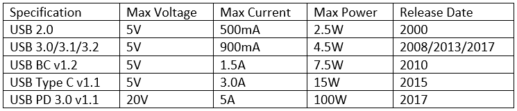
The only bit that was now missing, was the protocol that could be implemented to enable higher power delivery over the new Type C interconnect. The USB Power Delivery (PD) Spec was consequently introduced in 2012 which with the Type-C connector addressed the growing needs of power-hungry applications. It increases the maximum power level on the USB interconnect to 100W. The key evolution of power delivery over the USB interconnect is summarised below:
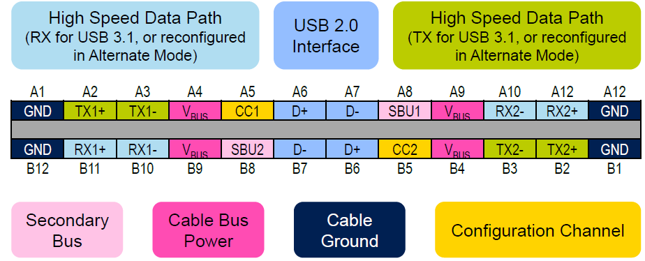
The actual power delivery over the USB Type C interface is determined by the use of the CC connection
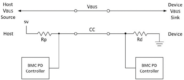
For the basic USB Type-C applications, 5V devices can be powered with up to 3A of current (15W) using the CC pin but without the need for USB PD control. Rather than sending configuration data over the CC pin, the pin is pulled up to the 5V supply rail. The amount of current is controlled by the pull-up resistor Rp and setting it to specific values sets the device to draw either 0.9A (56kΩ), 1.5A (22kΩ) or 3A (10kΩ). For devices making use of USB Power Delivery, communication is exchanged over the CC pin. This communication configures the right power between the charger and device, allowing for up to 100W of power using 20V and 5A.
Great care needs to be taken with this point! There are MANY unscrupulous companies that promote Type-C ‘USB-PD’ cables to the unwary, but these may be limited to 15W or less.
Fast Charging Process
Today's smartphones and other USB devices are increasingly equipped with intelligent fast charging technology. Smart phone charging current is controlled by the phone, not the charger. The smart phone will detect the load capability of the charger, and only allows the charger to supply a higher current when the charger has the capacity to source that power. If the designed charger output current is too small, then the phone will limit the charging current supplied and charging time is consequently reduced. This is the reason we need high-power chargers to complement higher performance products. However, a higher performance charger may also have additional benefits. For example, when a smart phone supporting up to 5V 1.5A input is charged by a 5V 1A charger, only 1A can be supplied to the phone. Not only is the charging speed slow, but the charger may also be running hot as it’s working at max output. In comparison, when it is charged by a 5V 2A charger, the phone will control the charging current to be at 1.5A, which also leaves the charger some load margin. The end result is faster charging where the charger counter-intuitively may not get as hot.
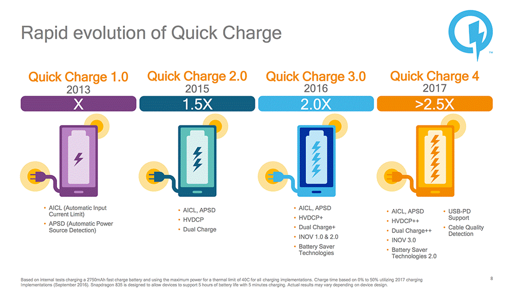
The key to improving charging speed is to increase the charging power. Ohms Law is used to derive that the Power (W) = Current (A) x Voltage (V), so when the charger output voltage is fixed at 5V, only the current can be increased for power improvement. However, the popular Micro USB interface and associated data cable were limited to 2A peak current as noted above, so 10W was the fast charge power delivery limit at that time. In fact, 5V/2A was the limit of Qualcomm's original Quick Charge 1.0 technology.
We know that as the mobile phone market continued to evolve, large screen smart phones began to emerge with even larger batteries to sustain the consumer run-time expectations. Fast charging became a key selling point to enhance the user experience, but how could this be delivered? It should be noted that in battery charging protocols, the charging current is not always the same. When the phone battery is low, it will be charged at peak current, which is called the Bulk Charge stage. When the battery level reaches 60% to 80%, the smart phone will send a signal to the charger to reduce the charging current, in order to protect the battery, reduce losses and reduce heat. In this latter stage, the charging power is greatly reduced. This is known as Absorption Charge stage. When battery is around 95% the charging will enter the last stage – the Float Charge, which brings the battery all the way through and maintains the 100% state of charge. It was therefore noted that faster charging could be delivered with the use of variable voltage to support the different charging stages and QC 2.0 was born.
QC2.0 most significantly changed the charging voltage, raising the years of conventional static 5V to a dynamic 9V/12V/20V, whilst keeping the same 2A max charging current. This realised an 18W high power transmission over the existing USB (Micro) interconnect and cable. As 9V 1.0A has the same power as a 5V 1.8A, but the current is reduced by over 1/3, so the conduction loss at the interface and cable are reduced.
This was great, but there was an issue; although the increased voltage enabled delivery of higher power, the efficiency drops with increased voltage. Most of the inefficiency energy is converted into heat which was the limiting factor on the uses of the 20V voltage level. For the 5V/9V/12V profiles remaining, the voltage steps were large so further efficiency savings could be found with the uses of smaller voltage steps for optimised charging. This resulted in Qualcomm introducing Intelligent Negotiation for Optimum Voltage (INOV) to set the voltage at steps of 200mV to allow the charger to find the most suitable charging voltage. This is the basis of QC 3.0. The minimum voltage can be as low as 3.6V and the maximum voltage is up to 20V. QC 3.0 is backward compatible with QC 2.0. At the same time, with the more mature Type C interface, the number of contacts on the Type C interface is several times that of the Micro USB interface, which greatly increases the current level it can withstand. Hence QC 3.0 can fully utilise the Type-C interface to replace the Micro USB interface, and raised the maximum charging current to 3A.
In 2017 Qualcomm then announced QC 4.0. This is fully compatible with USB-PD and raised the power level from 18W to 28W. However, this was not backwards compatible with earlier QC versions, which maybe an issue of the charger is to support legacy phones. QC 4.0+ was then introduced which also provides legacy QC compatibility. The 5V profile has a maximum current output 5.6A, the 9V profile has a maximum current output 3A, and the step voltage is further subdivided to 20mV steps between 3.6V and 20V.
Besides Qualcomm, many other companies were inspired to create their own fast charging solutions. For example, MediaTek’s Pump Express, Samsung’s Adaptive Fast Charging, Huawei’s Super Charge, Lenovo/Motorola’s Turbo Power. The list goes on. However, the basic principles of these fast charge technologies are similar: the charger and the phone begin with the normal 5V charging; then the charger and the smartphone communicate to identify each other; if the phone supports fast charging protocol, after receiving the right signal the charger will begin to supply higher power to the phone.
USB PD Evolution and Fast Charging Convergence
With the motivation of reducing e-waste in the future by removing the need for chargers with various ratings for different products, USB PD has evolved and parallel with USB 3.1 Gen 2 to produce a single charging standard that could be used across all USB devices; high speed and high power. Due to the power rating, USB-PD can now power hard drives, printers, and displays, as well as larger portable electronics like laptops. However, not only do specially rated USB cables for the highest power modes need to be used, but the protocol had to be enhanced. USB PD 2.0 therefore introduced some changes to the way that power ratings between devices are handled. The old set of Power Profiles were removed in PD 2.0 and replaced by Power Rules that allow for a wider range of current negotiations. PD 3.0 then made some further tweaks to enhance power delivery, but the Power Rules are the same as PD 2.0 as detailed below:
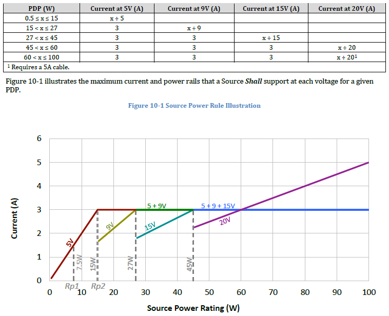
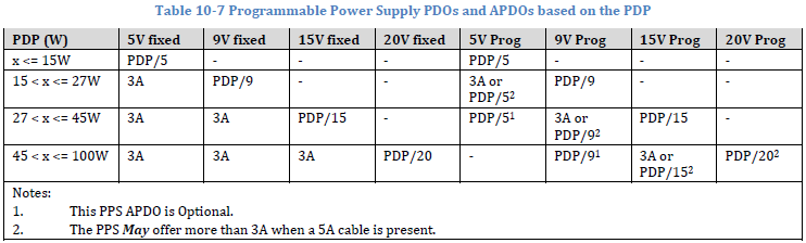
Sources supplying more than 15W offer voltages of 5V and 9V, whilst those supplying more than 27W offer 5V, 9V and 15V and those supplying more than 45W offer 5V, 9V, 15V and 20V. The maximum 100W power supply is achieved with 20V and up to 5A, with the need of a 5A rated cable. All of the other modes are limited to 3A.
In order to standardize the fast charge standard, the USB-IF then had an important update to the PD 3.0 specification in Jan 2017, moving to PD 3.0 v1.1 in which a feature called ‘Programmable Power Supply’ (PPS) was introduced. The PPS is a power supply whose output voltage can be programmatically adjusted in small increments over its advertised range. The programming step size is 20mV/step. The PPS also has a programmable output current fold back and a programming step size of 50mA/step which makes this highly flexible.
The capabilities of the PPS are exposed by the Programmable Power Supply APDO. Table 10-7 shows the Programmable Power Supply APDOs that Shall be offered for a given PDP. The PDP (PD Power) represents the output power of a Source, as specified by the manufacturer and expressed in Fixed Supply PDOs. PDO (Power Data Object) and APDO (Augmented Power Data Object) are Data Object used to expose a Source Port’s power capabilities as part of a Source Capabilities Message. For further detail on this, see this article: https://www.linkedin.com/pulse/usb-pd-30-v11-programmable-power-supply-pps-solutions-andy-richardson/
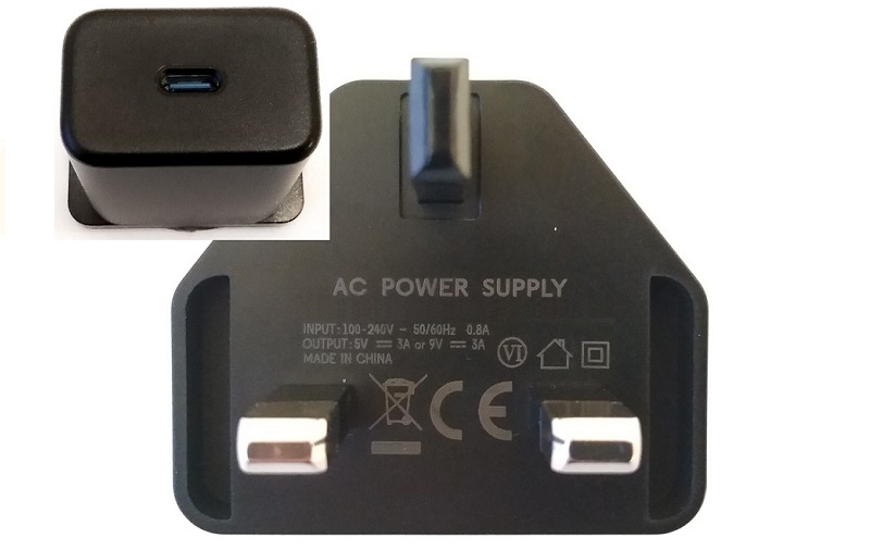
The importance of PPS from a fast charging perspective is that apart from the high voltage low current fast charge method represented by Qualcomm QC, MediaTek PE, and Huawei FCP, there also exists a low voltage high current fast charge process, as implemented by OPPO VOOC and Huawei SCP. PD 3.0 v1.1 is therefore able to provide a standard protocol that can unify the many different proprietary fast charging protocols from both worlds utilising the PPS feature, whilst also being backwards compatible with the basic USB profiles utilising static 5V when the USB PD protocol is not required. This results in a truly flexible charger able to support all product data and power requirements as negotiated with the specific product. An example of a USB-PD charger with PPS support able to deliver up to 27W from Salom is illustrated below. It can operate at 5V/3A and 9V/3A under PDO mode, as well as having 20mV step from 3V and 50mA step from 0A under APDO mode. Dimension is 52mm x 40mm x 26mm.
Summary
As we mentioned at the start of the article, USB 3.x, Type C and USB PD do not always feature together. Just because a product has a Type C interface, this does not mean it can support USB 3.x with 5Gb/s + and sink 100W of power. In fact, most products are still USB 2.0. limited to 15W of power. Various cables and fast chargers will continue to be promoted, but the risk of less than optimal performance is great. This ultimately reflects badly on a device manufacturers brand, so what’s the answer?
First and foremost, there needs to be greater consumer education, which is ultimately then intent of such articles as this, and always read the detail and purchase genuine products backed by a reputable brand. Lower cost will often mean lower performance, especially with the implementation of more complex power solutions. Furthermore, as the charging performance is dictated by the connected device in the negotiation stage, it’s quite feasible for device manufacturers to utilise the smarter protocols available today to even implement peripheral identification mechanisms, so that non-original chargers purporting to be compliant to the defined standards will not actually be enabled fast charging the device.
Although USB ports and connectors are often color-coded to distinguish their different functions and USB versions, however, the colour codes are not part of the USB specification, although the following is commonly used.
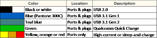
Because it is not in the standard, in real products the colour can vary between manufacturers. So, a “black” coloured USB could be 5Gbps or 10Gbps port too. This is fine as the customer is getting more speed. However, the danger is there is no guarantee that a “blue” coloured port must be a USB 3.1 port, it could be 480Mbps too! To be sure, the port always needs to be tested for its real speed. Watch this space!
Salom has a 40+ year history in the design and manufacture of power supply products that meet the most stringent and latest industry requirements. We have extensive experience with the application of the many varied fast charging protocols to all areas of the power supply industry and are a power partner of choice for many global brands. For further advice specific to your products, please contact us and we will be pleased to discuss your power needs.